Sunday 4 December 2011

CRDI


PRINCIPLE
Solenoid or piezoelectric valves make possible fine electronic control over the fuel injection time and quantity and the higher pressure that the common rail technology makes available provides better fuel atomisation. In order to lower engine noise, the engine's electronic control unit can inject a small amount of diesel just before the main injection event ("pilot" injection), thus reducing its explosiveness and vibration, as well as optimising injection timing and quantity for variations in fuel quality, cold starting and so on. Some advanced common rail fuel systems perform as many as five injections per stroke.[6]
Common rail engines require very short (< 1 s) or no heating up time at all[citation needed] and produce lower engine noise and emissions than older systems.
Diesel engines have historically used various forms of fuel injection. Two common types include the unit injection system and the distributor/inline pump systems (See diesel engine and unit injector for more information). While these older systems provided accurate fuel quantity and injection timing control, they were limited by several factors:
  • They were cam driven and injection pressure was proportional to engine speed. This typically meant that the highest injection pressure could only be achieved at the highest engine speed and the maximum achievable injection pressure decreased as engine speed decreased. This relationship is true with all pumps, even those used on common rail systems; with the unit or distributor systems, however, the injection pressure is tied to the instantaneous pressure of a single pumping event with no accumulator and thus the relationship is more prominent and troublesome.
  • They were limited in the number and timing of injection events that could be commanded during a single combustion event. While multiple injection events are possible with these older systems, it is much more difficult and costly to achieve.
  • For the typical distributor/inline system, the start of injection occurred at a pre-determined pressure (often referred to as: pop pressure) and ended at a pre-determined pressure. This characteristic resulted from "dummy" injectors in the cylinder head which opened and closed at pressures determined by the spring preload applied to the plunger in the injector. Once the pressure in the injector reached a pre-determined level, the plunger would lift and injection would start.
In common rail systems, a high pressure pump stores a reservoir of fuel at high pressure — up to and above 2,000 bars (29,000 psi). The term "common rail" refers to the fact that all of the fuel injectorsare supplied by a common fuel rail which is nothing more than a pressure accumulator where the fuel is stored at high pressure. This accumulator supplies multiple fuel injectors with high pressure fuel. This simplifies the purpose of the high pressure pump in that it only has to maintain a commanded pressure at a target (either mechanically or electronically controlled). The fuel injectors are typically ECU-controlled. When the fuel injectors are electrically activated, a hydraulic valve (consisting of a nozzle and plunger) is mechanically or hydraulically opened and fuel is sprayed into the cylinders at the desired pressure. Since the fuel pressure energy is stored remotely and the injectors are electrically actuated, the injection pressure at the start and end of injection is very near the pressure in the accumulator (rail), thus producing a square injection rate. If the accumulator, pump and plumbing are sized properly, the injection pressure and rate will be the same for each of the multiple injection events.

FUEL INJECTION

DIESEL FUEL INJECTOR


TURBO CHARGED ENGINES


Most of new generation diesel engines come with turbochargers and we call it turbocharged diesel engine. A turbocharger is a unit combined with a compressor and turbine coupled on same axle. Hot gases with high velocity are output of combustion stroke which are directed to exhaust. In case of turbocharged engines, this exhaust is directed to turbine. With high velocity and pressure of exhaust gases turbine rotates, on other side of turbine a compressor is attached which compresses the fresh air to engine to high pressure and high temperature.
As temperature of inlet gases increases its overall volume going inside a combustion chamber reduces.  Here an intercooler helps to reduce temperature of inlet air, now this air is at low temperature and high pressure. For same opening of inlet valve because of high pressure more air enters inside cylinder, in other words more CHARGE goes to combustion. This helps in giving higher output power with reduced emissions. Till now we are known to turbocharged diesel engines, why not petrol turbocharged engines, the only reason is compression ratio for diesel and petrol engines.
As more charge enters in combustion cycle, overall compression ratio increases for turbocharged engines. There are many advantages of turbo-charging petrol engines and few disadvantages too. Turbocharger increases overall engine temperature, and thermal stresses on engine block which affects badly to total engine life. But to meet future euro emission norms manufactures like Ford found a smart technology called Ford Eco-Boost engines, Fiat named it as T-Jet engines. Advantages of turbo-charging petrol engines are, we get higher power from small capacity engines, e.g. 1.4 liter engine give power output of 1.6 liter engine.
Recent example of such engine in Indian market is Fiat Linea T-Jet 1.4 which has power output of 114bhp. Not only overall power out but also many more advantaged of turbo petrol engines. When 1.4 liter engine gives output of 1.6 liter engine, the weight of car reduces and hence more miles per gallon with better performance. Increase in overall combustion temperature makes these engines are environment friendly. Ford claims with eco-boost engines there is 20% increase in fuel efficiency, 15% less COemissions and improved overall engine performance.
New Linea T-jet follows same figures in case of fuel efficiency, emission norms and overall engine performance. Till now only engines displacing 1.4 liters and above are in the market with turbocharged gasoline technology. Soon there will be bang with small capacity engines with better fuel economy and reduced emission to follow Euro 6 norms. Turbo charging : A way ahead for petrol engines.


MPFI

MPFI:
M.P.F.I. means Multi Point Fuel Injection system. In this system each cylinder has number of  injectors to supply/spray fuel in the cylinders as compared to one injector located centrally to supply/spray fuel in case of single point injection system.


Advantage of M. P. F. I.

(1) More uniform A/F mixture will be supplied to each cylinder, hence the difference in power developed in each cylinder is minimum. Vibration from the engine equipped with this system is less, due to this the life of engine components is improved.

(2) No need to crank the engine twice or thrice in case of cold starting as happens in the carburetor system.


(3) Immediate response, in case of sudden acceleration / deceleration.

(4) Since the engine is controlled by ECM* (Engine Control Module), more accurate amount of A/F mixture will be supplied and as a result complete combustion will take place. This leads to effective utilization of fuel supplied and hence low emission level.

(5) The mileage of the vehicle will be improved.


ECM ( Engine Control Module) and its function

The function of ECM is to receive signal from various sensors, manipulate the signals and send control signals to the actuators.

Sensors; Sensing different parameters (Temperature, Pressure, Engine Speed etc.) of the engine and send signal to ECM.

Actuators; Receives control signal from ECM and does function accordingly (ISCA, PCSV, Injectors, Power Transistor etc.)

Case I: If ECM fails to send control signal to all actuators then the engine won't get started.

Case II: If ECM fails to service from all sensors then also the engine won't get started. 

CARBURETTOR


Heat Engine Essentials


Heat Engine Essentials
  • A Heat Source
  • A Working Substance (working fluid)
  • Mechanical work (power) output
  • A Working Cycle
  • A Heat Sink


Work Output = Heat Supplied - Heat Rejected

W = Qs - QR
So efficiency
  = W / Qs

where


ENGINE - VARIOUS POSITIONS


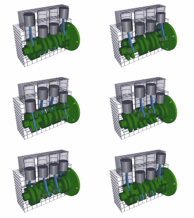
Vertical - Inline - 4 cylinder
V 6 Engine (6 cylinder)

FLAT - 4 


IC ENGINE COMPONENTS


ENGINE CYLINDER

IC ENGINE
CRANKSHAFT


WORKING OF CAR ENGINE


4 - STROKE CYCLE PETROL ENGINE

WORKING OF 4-STROKE CYCLE


2 -stroke engine Working